The driving technology of new energy vehicles has a big difference with traditional internal combustion engine vehicles, and one of them has a great development prospect. This is the hub motor technology. The following small series will introduce you to the principle and structure of this new technology.
The principle and structure of the hub motor - principle
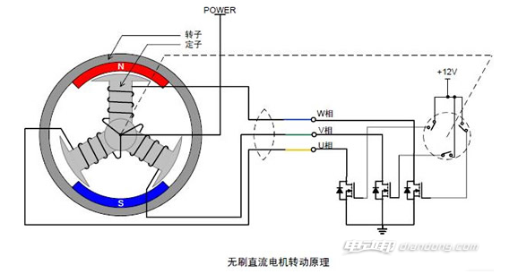
Before the brushless motor starts, it is necessary to use the sensor to know the relative position of the rotor and the stator. The non-inductive motor directly measures the back electromotive force of the motor and knows the position of the rotor. The controller drives the power tube for commutation. Although the memory can record the relative position of the stator and rotor, it is impossible to understand the waveform of the motor winding back electromotive force for a very slow rotating system. When the motor reaches a certain speed, the peaks and valleys of the motor are limited by a certain angle, and the motor is turned off when braking. Therefore, a hub motor using a magnetic sensor is the mainstream. The principle of the hub motor is that the red magnetic steel rotor is in the dead angle position, and the winding above the blue magnetic steel rotor is energized to get out of the dead angle. The motor shown in Figure 2 has no dead angle. As long as the position of the rotor is known, it knows how to drive the power tube.
The motor shown in Figure 1 and Figure 2 looks like a linear motor. The winding power is like using food to lure the dice (magnet steel) to keep running, but it always keeps a distance. It is more powerful and heavier. The structure is simple and low noise. Magnetic manual gear clutch high speed brushless hub motor Reduces the power required by three large and thin 2 mode steel gears. When the vehicle needs to be slid, the shaft, the piston and the hook of the shaft clutch transmission are pulled by the eccentric clutch handle, so that the outer rotor end cover of the motor gear is displaced, and the motor gear is separated from the transmission gear. Do not use the motor magnetic reset to achieve manual gear engagement when sliding, the clutch mechanism is simple, eliminating the overrunning clutch.
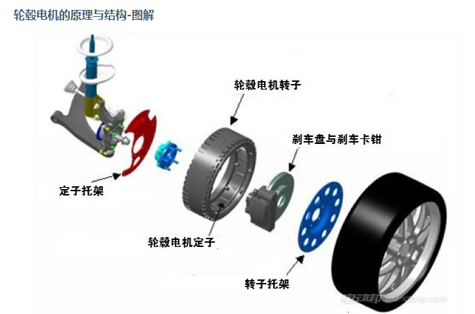
Principle and structure of the hub motor - structure
一、The structure of a three-phase asynchronous motor consists of a stator, a rotor and other accessories.
(一)Stator (stationary part)
1、Stator core
Function: A part of the magnetic circuit of the motor and the stator windings placed on it.
Structure: The stator core is generally formed by laminating and laminating a silicon steel sheet having an insulating layer on the surface of 0.35 to 0.5 mm thick, and a uniformly distributed groove is punched in the inner circle of the core for embedding the stator winding.
There are several types of stator core slots:
Semi-closed groove: The efficiency and power factor of the motor are higher, but the winding and insulation are more difficult. Generally used in small low voltage motors.
Semi-opening groove: It can be embedded with molded windings, and is generally used for large and medium-sized low-voltage motors. The so-called forming winding, that is, the winding, can be placed in the groove before being insulated.
Open type slot: used to embed the formed winding, the insulation method is convenient, mainly used in high voltage motors.
2、Stator winding
Function: It is the circuit part of the motor, which is connected to three-phase alternating current to generate a rotating magnetic field.
Structure: It is made up of three identical windings with 120° electrical angles and the same arrangement of the team. The coils of these windings are respectively embedded in the slots of the stator according to certain rules.
The main insulation items of the stator windings are as follows: (to ensure reliable insulation between the conductive parts of the windings and the core and reliable insulation between the windings themselves).
(1)Insulation to ground: insulation between the stator winding and the stator core.
(2)Interphase insulation: insulation between stator windings of each phase.
(3)Interturn insulation: insulation between turns of each phase of the stator windings.
Wiring in the motor junction box:
There is a wiring board in the motor junction box. The six wire ends of the three-phase winding are arranged in two rows, and the three terminal blocks in the upper row are numbered 1 to 1 (U1), 2 (V1), and 3 from left to right. (W1), the three wiring posts in the lower row are numbered 6 (W2), 4 (U2), and 5 (V2) from left to right. The three-phase windings are connected in a star connection or a delta connection. All manufacturing and maintenance should be arranged according to this serial number.
3、Machine base
Function: Fix the stator core and the front and rear end caps to support the rotor, and play the role of protection and heat dissipation.
Construction: The base is usually cast iron, the large asynchronous motor base is usually welded with steel plate, and the base of the micro motor is made of cast aluminum. There is a heat dissipation rib on the outer surface of the closed motor to increase the heat dissipation area. The end caps of the protective motor have ventilation holes at both ends, so that the air inside and outside the motor can be directly convected to facilitate heat dissipation.
(二)Rotor (rotating part)
1、Rotor core of three-phase asynchronous motor:
Function: As part of the magnetic circuit of the motor and placing the rotor windings in the core slot.
Construction: The material used is the same as that of the stator. It is made of 0.5 mm thick silicon steel sheet and laminated. The outer surface of the silicon steel sheet is punched with evenly distributed holes for the rotor winding. The inner core of the silicon steel sheet that is behind the stator core is usually used to punch the rotor core. Generally, the rotor core of a small asynchronous motor is directly press-fitted on a rotating shaft, and the rotor core of a large and medium-sized asynchronous motor (with a rotor diameter of 300 to 400 mm or more) is pressed against the rotating shaft by means of a rotor bracket.
2、Rotor winding of three-phase asynchronous motor
Function: Cutting the rotating magnetic field of the stator generates induced electromotive force and current, and forms electromagnetic torque to rotate the motor.
Construction: divided into squirrel cage rotor and wound rotor.
(1)Squirrel-cage rotor: The rotor winding consists of a number of bars inserted into the rotor slot and two ring-shaped end rings. If the rotor core is removed, the entire winding is shaped like a squirrel cage, so it is called a cage winding. The small cage motor adopts a cast aluminum rotor winding, and is welded by a copper strip and a copper end ring for a motor of 100 KW or more.
(2)Wound rotor: The wound rotor winding is similar to the stator winding. It is also a symmetrical three-phase winding. It is generally connected in a star shape. The three outlet heads are connected to the three current collecting rings of the rotating shaft, and then passed through the brush and the external circuit. Join.
Features: The structure is more complicated, so the application of the wound motor is not as extensive as the squirrel cage motor. However, through the collector ring and the brush, additional components such as resistors are inserted in the rotor winding circuit to improve the starting and braking performance and speed regulation performance of the asynchronous motor. Therefore, equipment that requires smooth speed regulation within a certain range, such as Cranes, elevators, air compressors, etc. are used above.
(三)Other accessories for phase asynchronous motors
1、End cap: support.
2、Bearing: Connect the rotating part to the non-moving part.
3、Bearing end cap: protects the bearing.
4、Fan: Cool the motor.
二、The DC motor adopts an octagonal full laminated structure, which not only has high space utilization, but also can withstand pulsating current and rapid load current change when powered by a static rectifier. DC motors generally do not have series-excited windings and are suitable for use in automatic control techniques that require forward and reverse rotation. It can also be made with series excitation winding according to user needs. The motor with a center height of 100 to 280 mm has no compensation winding, but the motor with a center height of 250 mm and 280 mm can be made with a compensation winding according to the specific conditions and needs. The motor with a center height of 315 to 450 mm has a compensation winding. The shape and technical requirements of the motor with a center height of 500-710mm are in line with the IEC international standard, and the mechanical dimensional tolerance of the motor conforms to the ISO international standard.
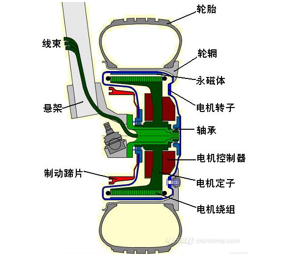
Are you saying something awkward? We don't need to know too much about the motor. The hub motor integrates the power unit, the transmission and the brake unit into the hub, which greatly simplifies the mechanical part of the electric vehicle. Although simplified, there are also some disadvantages, such as the consumption of electrical energy, which affects the comfort of operation. However, new technologies will slowly solve some problems.